Work shown
Deliverable 01
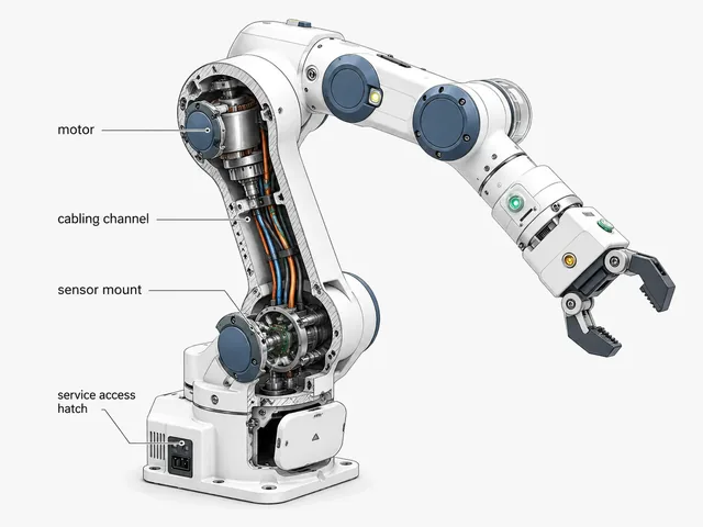
Arm and joint architecture map for motors, cabling, sensors and service access.
An automation equipment team needed a collaborative robot arm exterior that could protect joint motors and cabling while meeting factory-floor safety and serviceability expectations.

This case sits in the Robotics & Automation Equipment product type. Visit that page to confirm category fit before requesting a review.
Each theme maps to a common product-development decision: whether to fund engineering files, prototype, tooling, supplier sampling or pilot approval.
Automation equipment teams need covers that protect people and cabling without slowing down joint service or repair.
industrial robot enclosure design, cobot arm cover design, automation equipment industrial design.
Pinch-point risk, blocked service access, cable abrasion points and factory-inappropriate styling.
Review a collaborative robot exterior before prototype or supplier quoting.
Use this section to understand what changed through the project before comparing visuals.
| Project stage | What happened | Why it matters |
|---|---|---|
| Challenge | The team had validated joint motors and a kinematic chain, but no exterior cover direction that balanced safety, serviceability and factory-floor appearance. | Clarifies why the team could not simply approve the next spend. |
| Main concern | Covers built only around motor housings could create pinch points, block cable routing or complicate joint maintenance. | Shows the commercial or technical issue behind the project. |
| Approach | Align joint cover geometry, cable routing, service access and safety-edge detailing before committing to tooling. | Explains how form, structure, prototype route and supplier questions were connected. |
| Work completed | Arm and joint architecture map for motors, cabling, sensors and service access. Exploded view separating cosmetic covers from serviceable joint internals. | Makes the case more useful than a finished image alone. |
| Result | Clarified a serviceable, safety-conscious cover direction before deeper mechanical engineering investment. Reduced the risk of pinch points or blocked joint maintenance access. | Helps similar teams judge whether the same path fits their product stage. |
A useful example should show more than a finished image: inputs, structure, prototype notes and production preparation all matter.
Arm and joint architecture map for motors, cabling, sensors and service access.
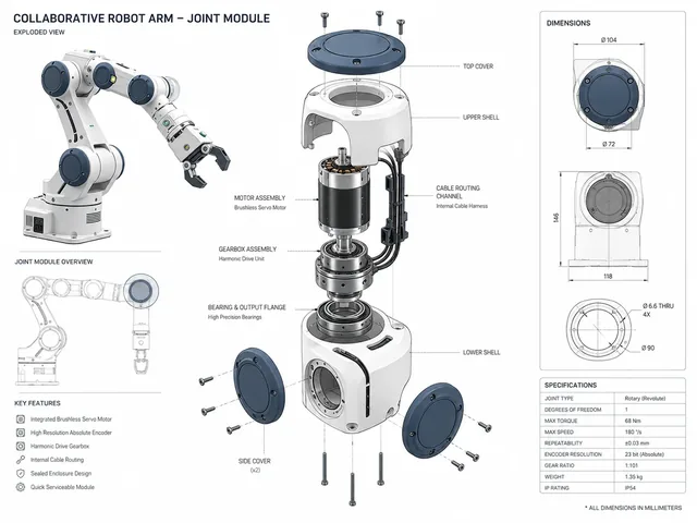
Exploded view separating cosmetic covers from serviceable joint internals.
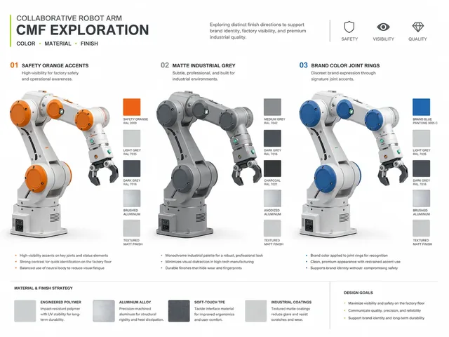
CMF direction for factory-floor visibility and brand consistency.
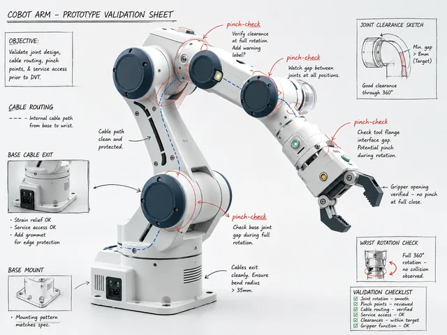
Prototype notes for pinch-point and cable-routing validation.
A useful case explains the project situation, not only the final visual.
The team had validated joint motors and a kinematic chain, but no exterior cover direction that balanced safety, serviceability and factory-floor appearance.
Covers built only around motor housings could create pinch points, block cable routing or complicate joint maintenance.
Align joint cover geometry, cable routing, service access and safety-edge detailing before committing to tooling.
Case pages separate inputs, completed work and approval gate so your team can judge whether a similar engagement fits your stage.
Product goal, current files, target user, constraints, references and supplier or prototype context when available.
Form, structure, 3D files, prototype, DFM or supplier-review outputs tied to the decision being made.
A practical next decision: fund engineering files, build prototype, revise before tooling, ask supplier questions or approve pilot conditions.
A strong industrial design case includes visual and technical outputs across form, structure, prototype and manufacturing preparation.
These client-safe outputs show the kind of project progress you should expect.
The first review gets faster when you can share the few details that define your current stage.